EMIS7311 Systems Engineering Design
1. Project Topic Description
1.1 Objective of the Project
In this project, we have proposed a video system to track the number of human in the video stream and check their faces to count them. The box would be formed around the faces, and a count number of the face will be displayed along with the time stamp of the identified face.
1.2. System Description
The use of a good image processing unit is important for the surveillance and security reasons. The system can be used for tracking the motions and action in the video that is being monitored. The system could also be used to load the already saved video, and check for the motion as per the time sequence and time stamps on them. These facilities and techniques are used in home and as well as commercial properties, and are implemented in almost every facility, so that a good security of the building and property can be ensured. The systems are also used for tracking the live activities of the workers in a commercial area, where the inspection of the production or management and service has to be checked live for any type of mishandling or other such concerns.
One of the very recent of such a live tracing video system has been identified where the system can be used as a child monitoring system. The system is installed in the child’s room, and any motion or activity can be tracked and checked using the system, and the alerts can be generated to be sent to the parents.
In this project, we have proposed a video system to track the number of human in the video stream and check their faces to count them. The box would be formed around the faces, and a count number of the face will be displayed along with the time stamp of the identified face.
The proposed system could be developed on number of software, and an attempt would be made to make the same on MATLAB, and the report will be made on the development of the software.
1.3. Description of Need for Development Phases
In the Phase I of development, the data and research material would be needed.
In Phase II, the software MATLAB, and the hardware would be needed.
In the Phase III, all the components, including software and hardware would be needed for testing.
2. Stakeholders and Needs
|
Stakeholder |
Need |
Product, Process or Service |
|
Developer/Product Creator |
Earning from the system sale |
System development |
|
Client/User |
Track human and count them in the system, surveillance, security system, load already saved video, monitor laces, track live activity, child monitoring, time stamping, reporting |
Tracking System on MATLAB |
3. External Systems
|
External System |
Need |
|
Home and Commercial Properties |
For general home security or office security |
|
Worker Environment and Commercial Area |
For checking and tracking live working and work progress |
|
Parents of Child |
For child tracking and monitoring, and security surveillance. |
4. Product and Process Models
|
Stakeholder Need |
Development Activity |
Defining Concepts |
Assessing Rqmts, Perf, or Capabilities |
|
Safety and Security |
Surveillance system |
Image and video processing |
Capture image ad process the same in the computer using MATLAB |
|
Track and Count Human |
Surveillance system |
Image and video processing |
Capture image ad process the same in the computer using MATLAB |
|
System Development |
Coding on MATLAB |
Video processing and signal processing |
Need of a system for development with MATLAB |
5. Operational concept scenarios
5.1. Entrance made by Individual
- User reaches the door and show complete face to the camera
- Camera detects the face and capture details including time, location, and count
- Automated voice plays to “Show identity card”
- RFID tagged ID presented in front of the camera by the user
- Camera reads tagged number and matches the database
- Individual allowed entering and door opens with a welcome automated voice “Welcome ‘name recorded in the tagged ID’”
- System records the data including all details of time, date, personal information etc.
5.2. Exit made by Individual
- User reaches the exit door and show complete face to the camera
- Camera detects the face and captures details including time, location, and count (in negative) and matches the data stored in the entrance attribute
- Automated voice plays to “Show identity card”
- RFID tagged ID presented in front of the camera by the user
- Camera reads tagged number and matches the database
- Individual allowed exiting and door opens with a thank you automated voice “Thank you ‘name recorded in the tagged ID’”
6. External System Diagrams
6.1. Sequence Diagram
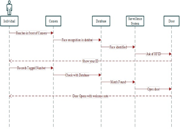
Figure 1: Sequence Diagram
(Source: Created by Author)
6.2. Scenarios and Sequence Diagrams (IDEF0 format)
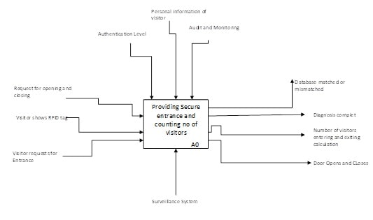
Figure 2: IDEF0 Format
(Source: Created by Author)
7. Objectives Hierarchy
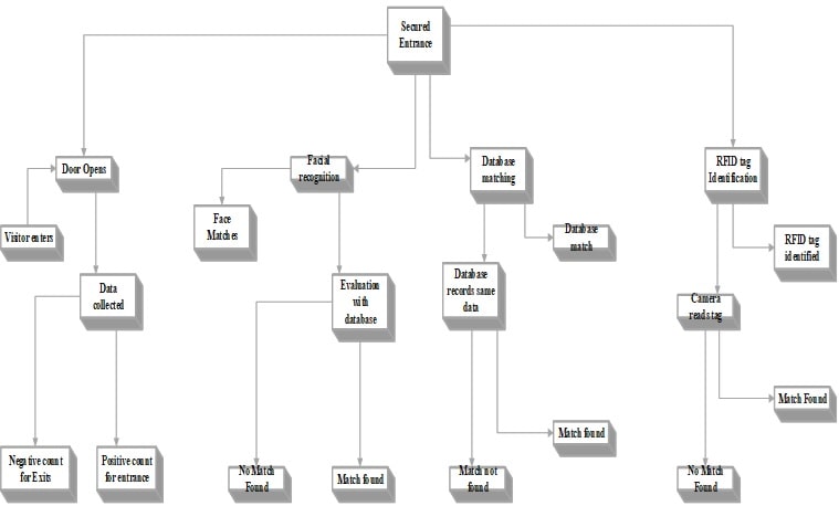
Figure 3: Objectives Hierarchy
(Source: Created by Author)
8. Stakeholders’ Requirements
Stakeholder Map
|
Internal
|
External
|
8.1 System Overview
The system will allow the venue to be completely secured and ask the individuals with proper credential to enter that venue. It will also identify the number of visitors present at the venue and what are they doing and it will be possible through the application of this surveillance system. This surveillance system will be incorporated with the latest camera, motion detectors and facial recognition systems. It will be beneficial for both the consumers and the venue operators who are supposed to handle the operations at the venue. It will be helpful in enhancing the security through comparing the input value with the stored value in the database and identify whether the legal visitor is entering the place or anyone else. Assumptions have been made regarding the application of the RFID technology enabling the better identification of the individuals entering the venue.
8.2 Applicable Documents
The needed documents will be the ownership of the technology ensuring the proper decision-making and ensuring who are the individuals those can enter the venue. The document related to the personal information of the individuals registered for the authority to enter the place and move around the venue for the accomplishment of some activities. Individuals at the executive position will have to make sure that there is enough availability of the data regarding the personality of the individuals calculating the digital signatures. The facial recognition will have to make sure that the personality of the individual does not changes with time in manner to compare the saved data with the individual as the system might not be able to match the record if the individual has changed his or her personality.
8.3. Requirements
Development Phase Requirements
Development phase will need the detailed information of the individuals granting access to move to the venue and ensuring that the data or information being provided belongs to the individual. Development phase will also ensure the policy regarding the privacy and security of the data or information being collected as the database will be collecting very personal and sensitive information including the digital signatures of the individual. The technologies such as camera, motion detector, digital signature detector, and others will be needed for the development of this project. Database management system is another requirement for the successful delivery of this approach and making the environment much secured. Development phase will be accomplished through the practice of the planning made identified in the prior of the project and will be developed accordingly.
Manufacturing Phase Requirements
Manufacturing phase will include the components with the group of the technicians who will be responsible for establishing the required network within the venue and setup the sensors, tagging and camera at several locations within the venue. Manufacturing phase will include the feeding of the data in the database management system those have been collected during the development phase of this project. The data will be captured within the database ensuring the comparison is specific and every objective of the project being delivered. MATLAB programming will be embedded considering the whole setup of the project and determination of the individuals entering the venue and leaving the venue.
Deployment Phase Requirements
The whole setup will need a venue for the deployment where every individual have RFID tagged ID or technologies are available for the determination of the data collected via the sensor. It will need a group of people managing the whole management system and who will make sure that everything goes around as per the planning. A group of technicians will be needed to make sure the deployment of the project is covering the targeted population and ensuring the deployment will be delivered in an efficient and effective manner.
Training Phase Requirement
Training will be necessary for the individuals entering the venue and managing the operational activities within the whole setup. The security department will also need training in how the options will be working during the growth and development phase of this project and ensuring that none of the intruder enters the venue without any authority. It will be helpful in bringing out the maximum efficiency of the project through ensuring that all the corners of the application being utilized by every stakeholder associated with this project.
Operational Phase Requirements
The data related to the individuals having access to the RFID tagged ID will be embedded within the system and the authentication will be determined through comparing the presented data at the door and data stored in the database management system. The above requirements will need to be accomplished before the accomplishment of this phase in manner to make sure that the phases of the project are being delivered in an efficient and effective manner. The functional requirements for this phase will be the cameras, motion sensors, facial recognition technologies, and the database management system in manner to make the system highly secured and allowing the accomplishment of the project covering the entire scope. The non-functional requirements will be that the system needs to be flexible ensuring the deletion and addition of data or information within the database management system. Other requirement will be the scalability as the number of visitors entering the venue might increase at some instances and thus, the cameras and database management system should be capable of handling these.
System Upgrade Phase Requirements
Constant upgrade will be made available regarding the new comers and the individuals who are disconnecting. Data or information will be added for the new comers and the same will be deleted for the individuals disconnecting with the department. Protection of the data and information will be another crucial objective for the project and thus, upgrades will be installed for the security and application of the database management system and sensors.
10. Alternative Evaluation and Decision Analysis
10. 1 Problem statement
The use of a surveillance camera is subjected to various threats. These problems mainly include the common technical difficulties that arises due to various reasons. Moreover, another problem of the surveillance camera is the need for checking the ping reply of the camera such that it can be effectively used for monitoring. Lastly, the need for firmware update is another problem which is faced during the use of a surveillance camera.
10. 2 Alternative options
- For the problem regarding the technical difficulties, the best alternative option is to hire staff for consecutive maintenance. This will remove the problem associated with the camera. Moreover, it is seen that rebooting the camera and verifying the connection is also a quick troubleshooter options for electronic devices.
- For the problem for checking the ping requests from the camera, the alternate options is to remote monitor the system constantly so that the reply from the camera is successfully captured and any problem can be mitigated.
- The need to get updates can be addressed by connecting to the VMS page of the network or by visiting the webpage of the device.
10. 3 Criteria
|
Criteria Value Range | |||||
|
Criteria |
Units |
Minimum |
Target |
Maximum |
Value Function Type |
|
1. Cost |
Dollar (Dollar) |
20 |
50 |
100 |
Linear RTS |
|
2. Reliability |
NA |
Less reliable |
Reliable |
Highly reliable |
Decreasing RTS |
|
3. Risk |
NA |
Low risk |
NA |
High risk |
Increasing RTS |
|
4. Impact |
NA |
Low impact |
NA |
High impact |
Increasing RTS |
|
5. Safety |
NA |
Less secure |
High security |
Highly secure |
Decreasing RTS |
For this criterion, five parameters have been used. These are cost, reliability, risk, impact and security. These five parameters will be aimed for the surveillance camera usages. Only the unit of the cost parameter is termed as dollars. The remaining parameters do not have any units mainly due to the fact that these are not real life values. Cost is termed as a linear RTS functions mainly due to the fact that it stays constant with increasing values of time. Reliability is termed as decreasing RTS mainly due to the fact that with increasing time, the reliability of the device decreases. Similarly, safety is also a decreasing RTS functions due to the same reason. Lastly, the risk and the impact of the system is termed as increasing RTS as for every increasing time value, various security implications can arise and hence the increasing RTS.
10. 4 Criteria value function
As we have the criteria and furthermore its esteem work, now we can without much of a stretch draw the chart of the esteem work for every basis. We have information is accessible in the frame minimum, target and maximum. In this the minimum value clarifies the value that in the worst case we should accomplish or keep up while in the maximum value, we will endeavor to accomplish the objective esteem with the goal that we can convey or make the best framework and the greatest esteem is the last range estimation of the criteria. In this graph the minimum, target and maximum values as x axis have been taken and time has been taken as the y-axis. The chose esteem is suitable in light of the fact that we have taken it as standard and we need to keep up it to make our framework solid, secure and powerful, so that while it can perform better and dependable for the customer. The functions are shown below:
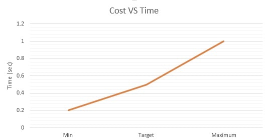
Figure 4
(Source: Created by Author)
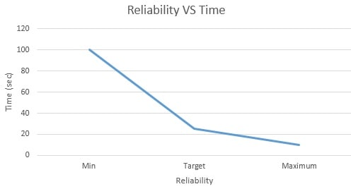
Figure 5
(Source: Created By Author)
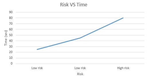
Figure 6
(Source: Created By Author)
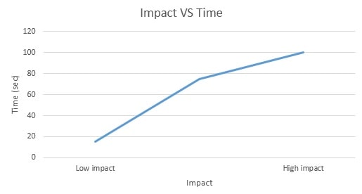
Figure 7
(Source: Created By Author)
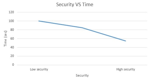
Figure 8
(Source: Created By Author)
10. 5 Criteria rank order
Due to the presence of various decision aspects, multiple criteria are selected. It is thus required to rank them on the basis of their priority. Essentially, ranking strategy gives the approximations of genuine weights of criteria when we know about the positions of the criteria. For this reason, this paper has calculated the rank of the various criteria involved with the surveillance camera. It is particularly important to compute the rank of the criteria to figure the heaviness of the criteria and rank total. So, the rank of the cost is 1, reliability rank is 3, risk rank is 4, in case of impact rank is 5 and safety rank is 2, these ranks are calculated for the Target values which we want to achieve in our project. The ranks are provided on ascending order of influence on the project.
|
Criteria |
Units |
Target |
Rank |
Value Function Type |
|
1. Cost |
Dollar (Dollar) |
50 |
1 |
Linear RTS |
|
2. Reliability |
NA |
Reliable |
3 |
Decreasing RTS |
|
3. Risk |
NA |
Less risky |
4 |
Increasing RTS |
|
4. Impact |
NA |
Less impactful |
5 |
Increasing RTS |
|
5. Safety |
NA |
High security |
2 |
Decreasing RTS |
10. 6 Criteria value weights
The relative criteria weights depend on the supposition that a weight– rank useful relationship exists between criteria ranks and criteria order. Such change depends on the distinctive recipes. The weights are very reliant on the elicitation strategy and there is no consent to which technique delivers more exact outcomes since the "genuine" weights stay obscure. Additionally, the gathering of leaders can't achieve concurrence on an arrangement of correct weights. The rank-order centroid (ROC) weight approach creates a gauge of the weights that limit the most extreme blunder of each weight by recognizing the centroid of every conceivable weight keeping up the rank order.
|
Criteria |
Rank order |
Rank sum |
Rank order centroid |
Rank exponent |
AHP |
|
1. Cost |
1 |
5 |
0.2 |
5 |
0.48 |
|
2. Reliability |
3 |
3 |
0.05 |
3 |
0.45 |
|
3. Risk |
4 |
2 |
0.1 |
2 |
0.42 |
|
4. Impact |
5 |
1 |
0.06 |
1 |
0.47 |
|
5. Safety |
2 |
4 |
0.04 |
4 |
0.44 |
10. 7 Criteria value weights and alternate values
The relative criteria weights depend on the supposition that a weight– rank utilitarian relationship exists between criteria ranks and criteria order. Such change depends on the distinctive recipes. The weights are exceptionally subject to the elicitation method and there is no assertion as to which method creates more precise outcomes since the "genuine" weights stay obscure. Additionally, the gathering of leaders can't achieve concession to an arrangement of correct weights. The rank-order centroid (ROC) weight approach delivers a gauge of the weights that limit the most extreme blunder of each weight by distinguishing the centroid of every single conceivable weight keeping up the rank order.
Alternate value: An assessment score is ascertained for every option by increasing the scaled esteem given to the option of that trait with the weights of relative significance straightforwardly allocated by chief took after by summing of the items for all criteria. The benefit of this method is that it is a corresponding straight change of the crude information, which implies that the relative order of greatness of the institutionalized scores stays measure up to
|
Alternatives and Scaled Criteria Results | ||||||
|
Criteria |
Units |
Rank Exponent Weights (z=___) |
Alt 1 |
Alt2 |
Alt3 |
Alt4 |
|
1. Cost |
Dollar |
5 |
30000 |
25000 |
28000 |
29000 |
|
2. Reliability |
3 |
7 |
7.5 |
6.5 |
7.5 | |
|
3. Risk |
2 |
5 |
5.2 |
7.7 |
8.7 | |
|
4. Impact |
1 |
9 |
8.4 |
8.3 |
9.6 | |
|
5. Safety |
4 |
2.9 |
2.6 |
2.8 |
2.8 | |
|
Alternative Scores | ||||||
|
Alternatives and Scaled Criteria Results | ||||||
|
Criteria |
Units |
Rank Reciprocal Weights (z=___) |
Alt 1 |
Alt2 |
Alt3 |
Alt4 |
|
1. Cost |
Dollar |
30000 |
25000 |
28000 |
29000 | |
|
2. Reliability |
7 |
7.5 |
6.5 |
7.5 | ||
|
3. Risk |
5 |
5.2 |
7.7 |
8.7 | ||
|
4. Impact |
9 |
8.4 |
8.3 |
9.6 | ||
|
5. Safety |
3 |
2.3 |
2.9 |
1.5 | ||
|
Alternative Scores | ||||||
|
Alternatives and Scaled Criteria Results | ||||||
|
Criteria |
Units |
Rank Order Centroid Weights (z=___) |
Alt 1 |
Alt2 |
Alt3 |
Alt4 |
|
1. Cost |
Dollar |
0.2 |
30000 |
25000 |
28000 |
23000 |
|
2. Reliability |
0.05 |
7 |
7.5 |
6.5 |
7.5 | |
|
3. Risk |
0.1 |
5 |
5.2 |
7.7 |
8.7 | |
|
4. Impact |
0.06 |
9 |
8.4 |
8.3 |
7.6 | |
|
5. Safety |
0.04 |
2 |
3.2 |
2.7 |
1.9 | |
|
Alternative Scores | ||||||
|
Alternatives and Scaled Criteria Results | ||||||
|
Criteria |
Units |
AHP Weights (z=___) |
Alt 1 |
Alt2 |
Alt3 |
Alt4 |
|
1. Cost |
Dollar |
0.48 |
30000 |
25000 |
28000 |
23000 |
|
2. Reliability |
0.45 |
7 |
7.5 |
6.5 |
7.5 | |
|
3. Risk |
0.42 |
5 |
5.2 |
7.7 |
8.7 | |
|
4. Impact |
0.47 |
9 |
8.4 |
8.3 |
7.6 | |
|
5. Safety |
0.44 |
2 |
3.2 |
2.7 |
1.9 | |
|
Alternative Scores | ||||||
10. 8 Scaled alternative and score
|
Alternatives and Scaled Criteria Results | ||||||
|
Criteria |
Units |
Rank Sum Weights |
Alt 1 |
Alt2 |
Alt3 |
Alt4 |
|
1. Cost |
Dollar |
5 |
30000 |
25000 |
28000 |
29000 |
|
2. Reliability |
3 |
7 |
7.5 |
6.5 |
7.5 | |
|
3. Risk |
2 |
5 |
5.2 |
7.7 |
8.7 | |
|
4. Impact |
1 |
9 |
8.4 |
8.3 |
9.6 | |
|
5. Safety |
4 |
2.9 |
2.6 |
2.8 |
2.8 | |
|
Risk | ||||||
The preferred Alternative is: ______
|
Alternatives and Scaled Criteria Results | ||||||
|
Criteria |
Units |
Rank Exponent Weights (z=___) |
Alt 1 |
Alt2 |
Alt3 |
Alt4 |
|
1. Cost |
Dollar |
5 |
30000 |
25000 |
28000 |
29000 |
|
2. Reliability |
3 |
7 |
7.5 |
6.5 |
7.5 | |
|
3. Risk |
2 |
5 |
5.2 |
7.7 |
8.7 | |
|
4. Impact |
1 |
9 |
8.4 |
8.3 |
9.6 | |
|
5. Safety |
4 |
2.9 |
2.6 |
2.8 |
2.8 | |
|
Alternative Scores | ||||||
The preferred Alternative is: ___2___
|
Alternatives and Scaled Criteria Results | ||||||
|
Criteria |
Units |
Rank Reciprocal Weights |
Alt 1 |
Alt2 |
Alt3 |
Alt4 |
|
1. Cost |
Dollar |
30000 |
25000 |
28000 |
29000 | |
|
2. Reliability |
7 |
7.5 |
6.5 |
7.5 | ||
|
3. Risk |
5 |
5.2 |
7.7 |
8.7 | ||
|
4. Impact |
9 |
8.4 |
8.3 |
9.6 | ||
|
5. Safety |
2.9 |
2.6 |
2.8 |
2.8 | ||
|
Alternative Scores | ||||||
The preferred Alternative is: ______
|
Alternatives and Scaled Criteria Results | ||||||
|
Criteria |
Units |
Rank-order Centroid Weights |
Alt 1 |
Alt2 |
Alt3 |
Alt4 |
|
1. Cost |
Dollar |
0.2 |
30000 |
25000 |
28000 |
29000 |
|
2. Reliability |
0.05 |
7 |
7.5 |
6.5 |
7.5 | |
|
3. Risk |
0.1 |
5 |
5.2 |
7.7 |
8.7 | |
|
4. Impact |
0.06 |
9 |
8.4 |
8.3 |
9.6 | |
|
5. Safety |
0.04 |
2.9 |
2.6 |
2.8 |
2.8 | |
|
Alternative Scores | ||||||
The preferred Alternative is: _0.1_____
|
Alternatives and Scaled Criteria Results | ||||||
|
Criteria |
Units |
AHP Weights |
Alt 1 |
Alt2 |
Alt3 |
Alt4 |
|
1. Cost |
Dollar |
0.48 |
30000 |
25000 |
28000 |
29000 |
|
2. Reliability |
0.45 |
7 |
7.5 |
6.5 |
7.5 | |
|
3. Risk |
0.42 |
5 |
5.2 |
7.7 |
8.7 | |
|
4. Impact |
0.44 |
9 |
8.4 |
8.3 |
9.6 | |
|
5. Safety |
0.47 |
2.9 |
2.6 |
2.8 |
2.8 | |
|
Alternative Scores | ||||||
The preferred Alternative is: __0.47____
10. 9 Decision analysis
Thus, it can be said that the preferred alternative score is 0.4. This will be utilized in addressing the implementation of the project for surveillance camera uses and monitoring. This will also help in meeting the needs of the stakeholders who are also associated with the project.
11. Functional and Physical Architecture
11. 1 Problem Statement
Security is always a concerning topic for any event or venue and it is necessary to make sure that the authorized individual enters the venue and there is not any further chaos or distribution in the event in future. Crime rate has been increasing drastically including the stealing, robbery, terrorist attacks, and many more and most of the events with higher budget are vulnerable to such threats. Development of a system that can ensure the security and safety of the individuals is the primary concern.
11. 2 Level 1:
The data will be collected into the database and as the person approaches the gate, the real-time data will start collecting for the data processing and comparing with the data stored in the database. The person’s digital signature will be identified and matched with the data stored in the database and thus, the facial recognition will be identified accordingly. This data will be matched with the database along with the RFID number in manner to make sure the identity of the individual. The user will have to show the identity at the gate and RFID tag will be detected ensuring the data or information of the individual. The next phase will be command used for opening gate that can be done automatically as the user identity matches the database. The whole system can be monitored via mobile device, laptop, or desktop. Whenever the individual enters the venue counting will added as ‘+1’ and the individual leaving the room another count will be added with the value ‘-1’. The following diagram shows the first level of architecture for the proposed design.
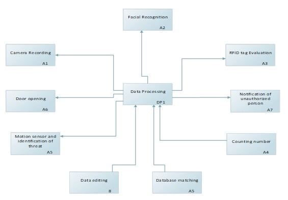
Figure 9: Level 1
(Source: Created by Author)
11. 3 Level 2
The second level system is demonstrating the real time data execution by the camera exploring more functionalities of the camera and how data will be processed through the data collected by camera. It will be capturing the face and digital signature of the individual and transferring the data to then Super Computer for the data processing. The collected data will be processed for identifying the identity of the individual and behavior of the individual whether he or she is a threat to the venue or not. Thereafter again, completing the whole objectives the computer will start counting the number as individual entering with the value ‘+1’ and individual leave with ‘-1’ and the rest of the process will flow as it was earlier.
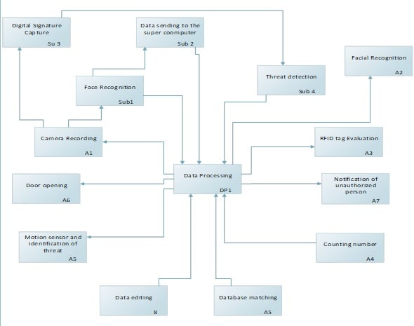
Figure 10: Level 2
(Source: Created by Author)
11. 4 Level 3
Level three subsystem has been the expansion of the threat detection system initialized from the camera and the image detection. The digital signature will be identified including the behavior of the individual and comparing with the preexisting calculation related to the detection of the aggressiveness and scanning for the weapons. The unauthorized individual will be further explored with the criminal records shred by the local government ensuring that the criminal is not entering the venue.
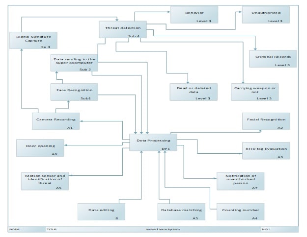
Figure 11: Level 3
(Source: Created by Author)
12. Physical Architecture
12. 1 Hatley-Pirbhai Architecture Definition
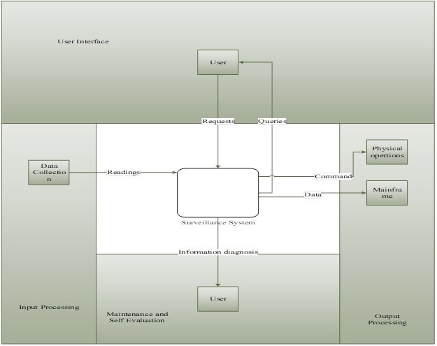
Figure 12: Hatley-Pirbhai Architecture
(Source: Created by Author)
12. 2 Morphological Analysis:
Morphological analysis is applied on segmented binary image for smoothening the foreground image. It is used on the structuring element of input image, creating an output image of same size. It processes the image based on shapes and it performs on image using structuring element. The structuring elements will be created with specified shapes (disk, line, square) which contains 1’s and 0’s value where ones are represents the neighborhood pixels. Dilation and erosion process will be used to enhance (smoothening) the object region by removing the unwanted pixels from outside region of foreground object. After this process, the pixels are applied for connected component analysis and then analysis the object region for counting the objects. It will also be focusing on the additional enhanced security feature of facial recognition, and threat detection system. Following data has been collected in relation with the generated system:
|
Functions |
Options | ||||||
|
Measure data |
Load Cell |
Proximity Sensor |
Magneto |
Image processor |
Light / Laser sensor |
Magnetic Sensor |
Camera |
|
Mount Sensors |
Pedal |
Shoe |
Crank Spider |
Crank Alarm |
Chain |
Chain Ring |
RFID tag setup |
|
Sample sensor Data |
Laptop |
Microcontroller |
Tablet |
Mobile device |
Smartphones |
Desktop | |
|
Supply Power |
Wall power or mains |
Battery |
Wind |
Solar |
Mechanical electricity converter | ||
|
Implementation of User Interface |
Dot matrix Display |
Seven segments display |
Touch screen |
LCD Display |
Voice commands |
Push buttons | |
|
Process Data |
Computer Program |
Smartphone Application |
Microcontroller | ||||
|
Data Transmission |
BLE |
Wired Communication |
Wi-Fi |
ANT+ |
GPS |
Custom Protocol | |
Table 1: Morphological Analysis table here
(Source: Created by Author)
10. Bibliography
Chandraker, M., Choi, W., Lau, E., Elsa, W.O.N.G. and Chen, G., NEC Hong Kong Ltd and NEC Laboratories America Inc, 2018. Mass transit surveillance camera system. U.S. Patent Application 15/637,533.
Chapman, W., 2018. Engineering modeling and design. Routledge.
Dandy, G., Daniell, T., Foley, B. and Warner, R., 2017. Planning and design of engineering systems. CRC Press.
Geng, J., Wong, V., Boswell, R.T. and Millar, G.M., Pelco Inc, 2016. Surveillance camera with integrated mounting feature. U.S. Patent Application 29/470,207.
Geng, J., Zhang, P. and Ma, Q., Honeywell International Inc, 2018. Surveillance camera. U.S. Patent Application 29/568,285.
Hitomi, K., 2017. Manufacturing Systems Engineering: A Unified Approach to Manufacturing Technology, Production Management and Industrial Economics. Routledge.
Hollnagel, E., 2017. FRAM: the functional resonance analysis method: modelling complex socio-technical systems. CRC Press.
Ippolito, L.J. and Ippolito Jr, L.J., 2017. Satellite communications systems engineering: atmospheric effects, satellite link design and system performance. John Wiley & Sons.
Jones, T.L., Robert Bosch GmbH, 2017. Surveillance camera with integral large-domain sensor. U.S. Patent 9,686,452.
Kerzner, H. and Kerzner, H.R., 2017. Project management: a systems approach to planning, scheduling, and controlling. John Wiley & Sons.
Knight, U.G., 2017. Power Systems Engineering and Mathematics: International Series of Monographs in Electrical Engineering (Vol. 3). Elsevier.
McBride, F.M. and Martin, W.A., Sensormatic Electronics Corp, 2017. Bubble for Surveillance Camera. U.S. Patent Application 14/802,788.
Mohankumar, M., Gopalakrishnan, V. and Yasotha, S., 2015. A Vlsi Approach For Distortion Correction In Surveillance Camera Images. ARPN Journal of Engineering and Applied Sciences, 10(9).
Niem, W., Niehsen, W. and Loos, H., Robert Bosch GmbH, 2015. Surveillance camera and method for calibrating the survelliance camera using a calibration tool. U.S. Patent 9,025,033.
Sablak, S., Robert Bosch GmbH, 2015. Omni-directional intelligent autotour and situational aware dome surveillance camera system and method. U.S. Patent 9,215,358.
Simonelli, M. and Quaglio, A., Myfox, 2015. Surveillance camera. U.S. Patent Application 29/507,172.
Stanton, N.A., Salmon, P.M., Rafferty, L.A., Walker, G.H., Baber, C. and Jenkins, D.P., 2017. Human factors methods: a practical guide for engineering and design. CRC Press.
Resources
- 24 x 7 Availability.
- Trained and Certified Experts.
- Deadline Guaranteed.
- Plagiarism Free.
- Privacy Guaranteed.
- Free download.
- Online help for all project.
- Homework Help Services
Testimonials
Urgenthomework helped me with finance homework problems and taught math portion of my course as well. Initially, I used a tutor that taught me math course I felt that as if I was not getting the help I needed. With the help of Urgenthomework, I got precisely where I was weak: Sheryl. Read More

