SIT123: Data Capture Technologies Lab Report 3
In this task, you will investigate a given data set, look for inconsistencies in the data and propose methods to fix them.
Task Objective
- Use the provided dataset HumidityDataset.CSV on collection of Humidity values for location X. The file is available here:https://drive.google.com/file/d/0B6VXEzM81LStczdRUjlnWjNEOEU/view
- Investigate the data for inconsistencies. These inconsistencies could include:
- Missing data, rows and column values
- Mismatched data fields
- Mismatched date formats
- Propose ways to fix consistencies, these fixes could include:
- Propose and use default values
- Remove missing rows
- Fix data format mismatches
- Fix the data
Task Submission Details
There are 2 questions in this task. Answer all of them in this document itself and submit to unit site.
Q1: Once you have cleaned your data, submit the cleaned data file to unit site with this document.
Inconsistencies found
Approach for fixing
Pros. and Cons of your approach
Sensing Motion Activity Sheet
Hardware Required
- Arduino Board
- USB cable
- HCSR505 PIR Passive Infra Red Motion Detector (https://tronixlabs.com.au/sensors/motion/hcsr505-pir-passive-infra-red-motion-detector-australia/)
- Male to Female Dupont Jumper Wires
Steps
1. Examine the motion sensor closely. Can you see a + sign at the base? This is the VCC pin, or the pin that should be connected to Arduino’s power pin. The middle pin on the sensor is the one that transfers sensor data. The last pin, with a - sign at the base is the Ground pin.
Connect your HCSR505 PIR Passive Infra Red Motion Detector to the Arduino board using the images & steps a, b and c included below for guidance.
- Pick a red male-female jumper wire and attach the female end to pin 1 (VCC pin) on the sensor. Plug the male end into the Arduino board’s 5V power pin.
- Pick a blue male-female jumper wire and attach the female end to pin 2 (DATA pin) on the sensor. Plug the male end into the Arduino board’s digital data pin 6.
- Pick a black male-female jumper wire and attach the female end to pin 4 (GND) on the sensor. Plug the male end into the Arduino board’s GND pin.
(These Red, Blue, Black colours don’t really matter. But it’s good to follow a standard for ease of use)
2. Connect your Arduino board to your computer using the USB cable.
3. Open your Arduino IDE
4. Download the provided code at https://github.com/FeifeiDeakin/HCSR505motion. If you download it in .zip format, you must extract it to a location on your computer after you download it.
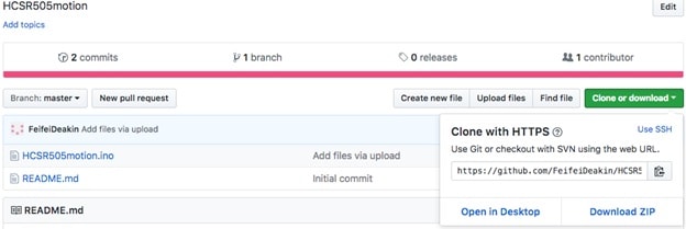
See: https://support.microsoft.com/en-us/help/14200/windows-compress-uncompress-zip-files for extracting zip files on Windows & https://support.apple.com/kb/PH25411?locale=en_US for extracting zip files on Macs.
5. Go to the Arduino IDE. Select “File -> Open” and it will open a dialog box.
6. Select the HCSR505motion.ino file inside the HCSR505motion folder & click Open.
7. In your Arduino IDE, click on the ‘Verify’ button. This will check for errors and compile your code.
8. Use the “tools” menu to check the port to which the Arduino board is connected. Once the right port is selected, it is possible to upload sketches to Arduino.
9. Now click the upload icon to upload the code to the Arduino board. If you get an error, check to be sure you’ve selected the correct device and port.
10. Open the Serial Monitor in the Arduino IDE by selecting Tools->Serial Monitor, or by clicking on the Serial Monitor icon.
11. Wave your hand in front of the motion sensor. Observe what’s printed on the Serial Monitor!
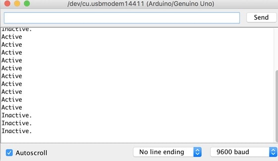
12. To get the data and save it, simply click on the Serial Monitor, Select all-> Then copy by CMD+C on Mac or Ctrl+C on Windows. Then paste to a text editor such as Notepad/Atom/Sublime Text and save it.
References
https://www.elecrow.com/wiki/index.php?title=HC-SR505_Mini_PIR_Motion_Sensor
https://docs.bsfrance.fr/documentation/10583_HC_SR505/HC-SR505.pdf
http://www.instructables.com/id/PIR-Motion-Sensor-Tutorial/
https://cdn-learn.adafruit.com/downloads/pdf/pir-passive-infrared-proximity-motion-sensor.pdf
Sensing Soil Moisture Activity Sheet
Hardware Required
- Arduino Board
- USB cable
- DFrobot Soil Moisture Sensor (https://tronixlabs.com.au/sensors/moisture/dfrobot-soil-moisture-sensor-arduino-compatible-immersion-gold-australia/ )
- Male to Male Dupont Jumper Wires
Steps
1. Find the DFrobot Soil Moisture Sensor from the sensor kit and attach the provided wires to the sensor. This sensor comes with 3x jumper cables.
2. Connect the DFrobot Soil Moisture Sensor to the Arduino board using the images & steps a, b and c included below for guidance.
- Analog output(Blue wire)
- GND(Black wire)
- Power(Red wire)
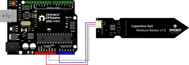
- Pick a red male-male jumper wire and attach one end to the red wire (female) on the sensor. Plug the other end into the Arduino board’s 5V power pin.
- Pick a blue male-male jumper wire and attach one end to the blue wire (female) on the sensor. Plug the other end of the male-male wire into the Arduino board’s Analog data pin 0 (A0).
- Pick a black male-male jumper wire and attach one end to the black wire (female) on the sensor. Plug the other end of the male-male wire into the Arduino board’s GND pin.
3. Connect your Arduino board to your computer using the USB cable.
4. Download the provided code at https://github.com/FeifeiDeakin/DFRobotSoilMoisture. If you download it in .zip format, you must extract it to a location on your computer after you download it.
5. Open your Arduino IDE.
6. Go to the Arduino IDE. Select “File -> Open” and it will open a dialog box.
7. Select the DFRobotSoilMoisture.ino file inside the DFRobotSoilMoisture folder & click Open.
8. In your Arduino IDE, click on the ‘Verify’ button. This will check for errors and compile your code.
9. Now click the upload icon to upload the code to the Arduino board. If you get an error, check to be sure you’ve selected the correct device and port.
10. Open the Serial Monitor in the Arduino IDE by selecting Tools->Serial Monitor, or by clicking on the Serial Monitor icon.
11. Expose the sensor to different moisture levels and see what values are printed on the Serial Monitor!
(Hint: you don’t need to stick the sensor into a soil mix to test it! An easy way is to put some wet tissue in a cup and stick the sensor into the wet tissue. Be careful when you test the Arduino board & sensors with water! Make sure you don’t spill any, and wipe any remaining water from the sensor after you finish the experiment)
References
https://www.dfrobot.com/wiki/index.php/Moisture_Sensor_(SKU:SEN0114)
https://www.dfrobot.com/wiki/index.php/Capacitive_Soil_Moisture_Sensor_SKU:SEN0193
Sensing Temperature and Humidity Activity Sheet
Hardware Required
- Arduino Board
- USB cable
- DHT22 Temperature and Humidity Sensor (https://tronixlabs.com.au/sensors/humidity/dht22-temperature-and-humidity-sensor-australia/ )
- Male to Female Dupont Jumper Wires
Steps
1. Connect your DHT22 Temperature and Humidity Sensor to the Arduino board. Refer to the images included below for guidance.
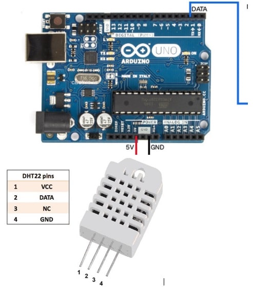
- Pick a red male-female jumper wire and attach the female end to pin 1 (VCC pin) on the sensor. Plug the male end into the Arduino board’s 5V power pin.
- Pick a blue male-female jumper wire and attach the female end to pin 2 (DATA pin) on the sensor. Plug the male end into the Arduino board’s digital data pin 2.
- Pick a black male-female jumper wire and attach the female end to pin 4 (GND) on the sensor. Plug the male end into the Arduino board’s GND pin.
- Sensor’s pin 3 is not used.
2. Connect your Arduino board to your computer using the USB cable.
3. Open your Arduino IDE
4. Go to https://github.com/adafruit/DHT-sensor-library and download the library to your computer by clicking ‘Download ZIP’.
2. Connect your Arduino board to your computer using the USB cable.
3. Open your Arduino IDE
4. Go to https://github.com/adafruit/DHT-sensor-library and download the library to your computer by clicking ‘Download ZIP’.
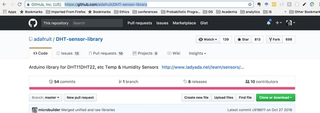
5. The .zip file you just downloaded is an external library. These have implemented functionality for DHT series of low cost temperature/humidity sensors. Using external libraries can save us from ‘reinventing the wheel’!.
6. Save the downloaded library. You should save all your Arduino libraries in one location, such as inside Documents/Ardiuno/Libraries
7. Go to https://github.com/adafruit/Adafruit_Sensor and download the library to your computer by clicking ‘Download ZIP’. Save it inside Documents/Ardiuno/Libraries
8. Download the provided code at https://github.com/FeifeiDeakin/DHT22tempHum. If you download it in .zip format, you must extract it to a location on your computer after you download it.
See: https://support.microsoft.com/en-us/help/14200/windows-compress-uncompress-zip-files for extracting zip files on Windows & https://support.apple.com/kb/PH25411?locale=en_US for extracting zip files on Macs.
9. Go to the Arduino IDE. Select “File -> Open” and it will open a dialog box.
10. Select the DHT22tempHum.ino file inside the DHT22tempHum folder & click Open.
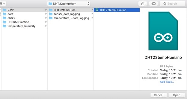
11. Add the libraries you downloaded to Arduino by selecting Sketch->Include library>Add Zip library. Select the downloaded zip libraries.
12. In your Arduino IDE, click on the ‘Verify’ button. This will check for errors and compile your code.
13. Use the “tools” menu to check the port to which the Arduino board is connected. Once the right port is selected, it is possible to upload sketches to Arduino.
14. Now click the upload icon to upload the code to the Arduino board. If you get an error, check to be sure you’ve selected the correct device and port.
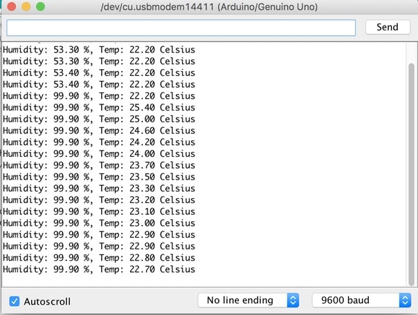
15. Open the Serial Monitor in the Arduino IDE by selecting Tools->Serial Monitor, or by clicking on the Serial Monitor icon.
16. Observe what’s printed on the Serial Monitor!
References
https://github.com/adafruit/RTClib
https://learn.adafruit.com/adafruit-data-logger-shield/using-the-real-time-clock-3
http://www.instructables.com/id/How-to-use-DHT-22-sensor-Arduino-Tutorial/
https://plot.ly/arduino/dht22-temperature-tutorial/
http://cactus.io/hookups/sensors/temperature-humidity/dht22/hookup-arduino-to-dht22-temp-humidity-sensor

